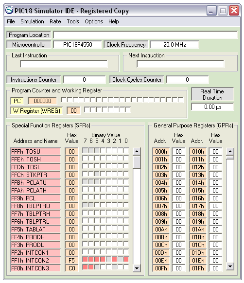
Figure 1: Oshonsoft PIC18 IDE interface
The settings
- Set the clock frequency by: double clicking on the 20MHz. Then, Figure 2 will be shown. Here, input your desired frequency and click ok.
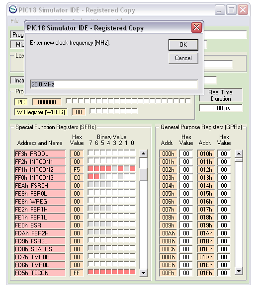
Figure 2: Setting of clock frequency of PIC18F
- Next, set the PIC18F series to be simulated by clicking on the PIC18F series after microcontroller.
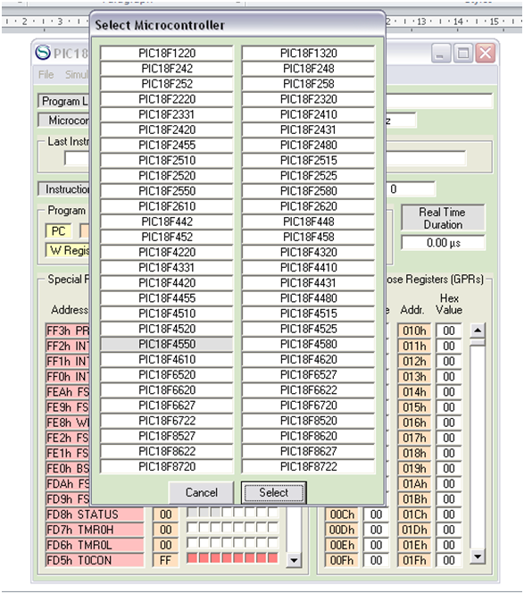
Figure 3: Selecting PIC18F model
- Before loading the program for simulation, set the speed of simulation : Rate -> Ultimate (for fastest simulation) .
- To load the program, File -> Load Program

Figure 4: Simulating with different speed
- In tools, you can bring out the peripherals you need that are in your system to simulate it virtually.
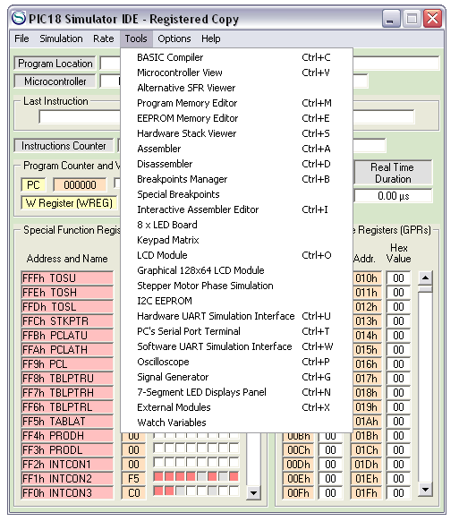
Figure 5: Peripheral tools and instruments that are provided
- Options allow you to tweak the peripherals, IDE layout, and the microcontroller to meet the specification of the hardware parts that will be used.
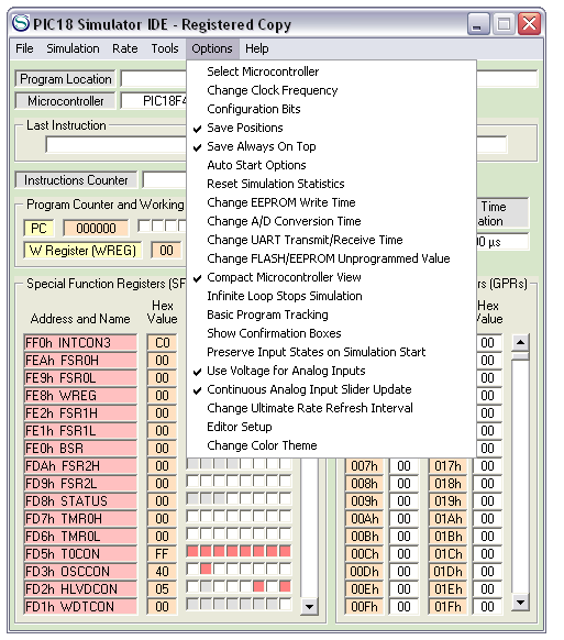
Figure 6: Changing the settings for peripherals, IDE and other schemes
Example
Using PIC18F Oshonsoft IDE Simulator, a program to light up an LED at PORTD,0 when a logic 1 is detected at PORTE,1 .
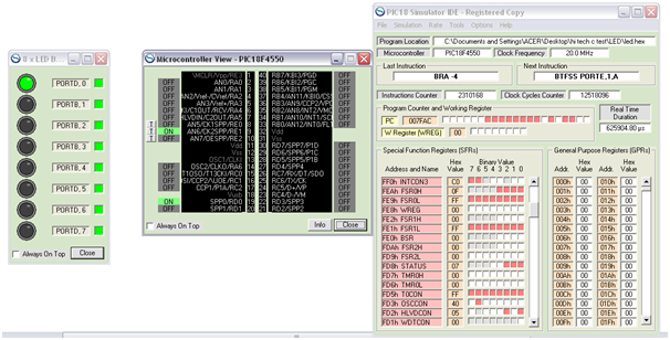
Figure 7: Example to detect a logic 1
No comments:
Post a Comment