Monday, August 15, 2011

Free uCOS-III for educational use and research

uCOS-III is the latest Real Time Operating System (RTOS) from Micrium. The source code can be downloaded through the link below.

uCOS-III

While, the books and project files for certain processors can also be downloaded. Below, is the link

uCOS-III Projects

Pong game using DE2


A cheap, simple yet elegant tool for hobbist and students


Engineering Assistant

7 segment display utility


7 segment display utility

7 segment display  utility

Calculate Delay in PIC

Calculate Delay in PIC


Stand alone SPBRGH calculator by K8LH

Stand alone SPBRGH calculator


Free Baud Rate Calculator for PIC

Free Baud Rate Calculator for PIC


40pin/ 28 PIC development board


Thursday, July 14, 2011

MikroC

MikroC is a C Compiler for PIC as well as some other microcontroller. It has large precompiled library to be used in accessing the peripheral that are connected the PIC microcontroller. MikroC has an independent IDE which doesn't need to be plugged in to MPLAB. In addition, MikroC IDE has numerous tools such as ASCII chart, EEPROM Editor, UART Terminal, GLCD Editor and etc which will further be described later.

Setting up MikroC project


  1. Click Next.


Figure 1: New Project Wizard


  1. Select the Device that you want to use. Click Next.


Figure 2: Choosing Device


  1. Select the clock frequency. Click Next.


Figure 3: Setting the clock


  1. Choose the location where the files are to be saved. Click Next.


Figure 4: Specifying the location of the file to be saved


  1. Here, you can choose to include all library provided by MikroC or select a few that you will be using if you know which has to be used. Click Next


All the libraries that are not used have to be removed by unselect all the libraries later.


Figure 5: Choosing the library


  1. Select Open Edit window to set Configuration bits. Click Finish.


Figure 6: Last step in new project Wizard


  1. Figure 7 will be prompt. Choose the appropriate configuration fuse settings. Click OK.


Figure 7: Project configuration fuse settings


  1. Add the related .c files to sources and .h to header files. Other files may also be added. You should have similar layout as Figure 8.


Figure 8: Project Manager


  1. Figure 9 shows the MikroC libraries. All libraries that are not used should be unselected. Otherwise, it might cause compilation error for some cases.


Figure 9: MikroC libraries


  1. Go under tools you will find the list of additional tools that might help you perform your codings.


Figure 10: Additional useful tools in MikroC


  1. Click Build. If your code is error-free, you should get Figure 11 stating Finished successfully.


Figure 11: Compilation status

Conclusion


Learning how to use a compiler such as MikroC would help beginners to build their project quickly as advance peripheral libraries are provided. These libraries are: USB, GLCD as well as Ethernet and etc.

Sunday, July 3, 2011

Using Serial UART

UART is an essential interface to PC. Below shows how to use and set the configuration bits in C18. The purpose of the codes below is to loop back to the Hyperterminal the word "Hello" to make sure the settings of the PIC works accordingly. OpenUSART() function is provided by C18 and it is used to set the neccessary registers in PIC18F series microcontroller.


For some that uses a USB to Serial converter, they are required to test the converter is working properly. Some have been reported not working. The converter can be test by connecting pin 2 and pn 3 together. This allows the data sent from Hyperterminal to loop back to the terminal. After this is done, the above codes can be used to make sure the serial is function properly.


Figure 1: Connecting pin 2 and pin 3 of seriall


Figure 2: Terminal showing the loop back

Conclusion


These test allows you to save time by debugging the necessary erroneous parts in your development.

Simple power supply for PIC MCU

The power supply for PIC is either 5V or 3.3V. Let us begin with simple 5V regulated power supply. Figure 1 illustrates Proteus simulation for the 5V supply. Note that the supply voltage to the 7805 has to be at least 2V from the regulated voltage. Thus, in this case, the supply voltage has to be 7V and above.

In some cases, you might want to use it with PIC24F and also dsPIC devices that needs 3.3V. Thus, it is better to have both 3.3V and 5V.


Figure 1: 5V using 7805


Figure 2 and figure 3 shows a simple circuit that will provide 5V and 3.3V. Here, a voltage divider is used to convert the 5V to 3.3V. The switch, SW1 can be replaced with a 3-pin connector. Thus, this will enable you to have, 5V, 3V and GND on the 3 pins.

Figure 2 shows direct output 5V from the regulator while Figure 3 shows the output from the regulator is passed through a voltage divider to get 3.3V.


Figure 2: Direct output from regulator


Figure 3: Output from a regulator through a voltage divider

Conclusion


Having 5V and 3.3V, power supply could be very handy. IC's such as PIC24F would require 3.3V while Max232 requires 5V. Therefore, in this case, you would require both 5V and 3.3V

Simulating PIC with Proteus

Simulating circuits in virtual environment can save both time and cost to produce the hardware. So far, Proteus provides a wide range of PIC simulation from PIC16F to dsPIC33F. It also enables the developer to check for the functionality as well as coding errors such as logical conditioning errors when coding.

Figure 1 shows the Proteus simulation environment.

  1. Click on component mode -> P to pick the devices.


Figure 1: Selecting a device in Proteus


  1. Figure 2 will pop up. Here, type the device for simulation. In this case, type PIC18F4550 in keywords. Then, click OK.


Figure 2: Pick the device


  1. Put the device selected in the blue box. Figure 3 shows the pin layout of the PIC18F4550.


Figure 3: PIC18F4550


  1. Other devices such as LED and resistors are added by repeating steps 1 to 3.


Figure 4: Adding resistor and LED


  1. After adding the necessary devices, connect them together by clicking on the end of one device to another device. Once this has been done, you should have the same layout connection as Figure 5.


Figure 5: Full circuit for simulation


  1. Double click on PIC18F4550 will bring up Edit Component GUI. Here, you can set additional settings for your PIC. Then, load the hex code generated by the MPLAB in Program File column and click OK.


The sample source code using C18 is provided below.


Figure 6: Configuration in PIC18F4550


  1. At the far left, where the simulation panel is located, click on run to begin the simulation. Alternatively, you can pause, halt as well as simulation by frame.


Figure 7: Simulation panel

Source Code


Conclusion


This simulation will provide another platform to test and debug your PIC program in virtual environment. In addition, the developer can focus in troubleshooting their codes without having to worry about their hardware failure.

Troubleshooting Pickit 2 Clone

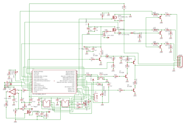
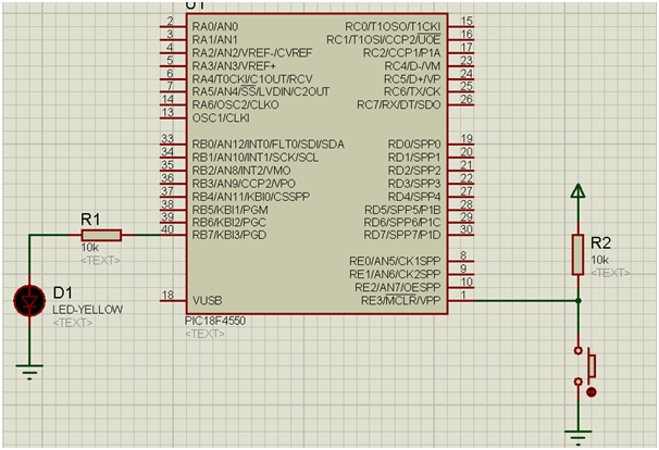
Pickit 2 is a multipurpose tool : PIC programmer, debugger, UART and Logic analyzer provided by Microchip and the schematics is provided in Pickit 2 datasheet.

Schematics:


Specifications:


  1. Easy to use Windows® programming interface for programming Microchip's Flash family of microcontrollers

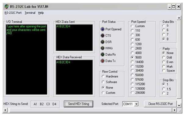
  2. UART Tool software for direct serial communications with a microcontroller RX/TX pins through the PICkit 2.

  3. Logic Tool software for simple logic signal stimulus and monitoring, with a 3-channel logic analyzer.

  4. PICkit 2 Programmer-To-Go support for programming devices without a PC.

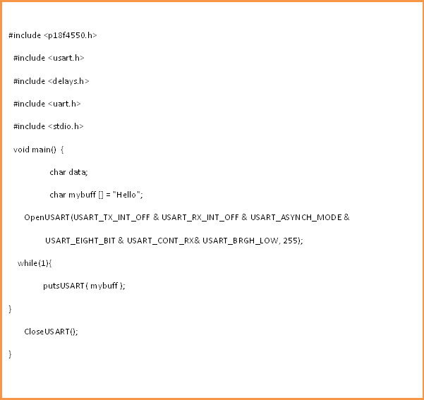
  5. Code Examples in assembly and C.


Test methods:


Hardware – based:


  1. Ensure that PIC18F4550 is programmed.

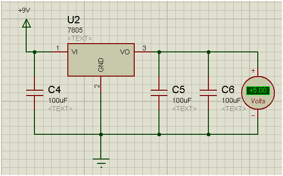
  2. The VPP generated voltage should be about 11V to 13V while VDD is 5V.

  3. The P MOS used need to be IRLML6402 to provide enough power to programming.


Software-based:


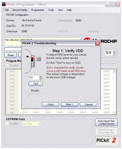
Pickit 2 Troubleshoot can be found in TOOLS -> TROUBLESHOOT.. After you have clicked on the button, a pop up menu as shown below will appear. Click on NEXT.


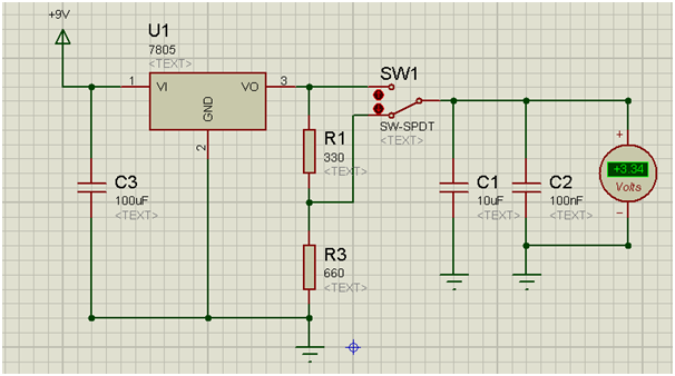
The first step of troubleshooting is to verify the VDD. For PIC18F, the VDD is 4.5V, while for PIC16F, it is about 3.6V. Click on TEST to measure the VDD. The VDD can be further verified by using a multimeter at pin 2 and pin 3 of the ICSP.


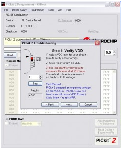
Once the TEST button is clicked,  there will be a message whether it passed the VDD test or failed. If the VDD test failed, then, it is necessary to check whether the installation of components is correct.


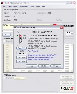
Assuming the VDD test has passed, we will go on to verify the VPP now. The VPP for PIC18F is about 12V. This can also be verified further using a multimeter. For PICKIT 2 clones, it is often caused by the MOSFET( BS250) which is most likely used as a substitute for IRLML6402. Here, you can also test for MLCR 'high' and 'low'.


Once the VPP test has passed, we will move on to troubleshoot the PGC and PGD using a frequency counter or frequency measurement equipment. The range of the frequency when it is toggled at 30kHZ is about 26 – 28kHz. You may also try to pull the PGC and PID pin to 'high' or 'low' and measure it with your multimeter.


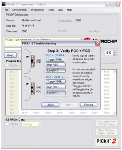
After everything has been done, click on the FINISHED button. Now, you are ready to use your pickit 2.

Conclusion


Pickit 2 is a great multipurpose tool that enables you to program and debug a PIC microcontroller. In addition, it also has a UART tool, and logic analyzer.