Figure 1 shows the Proteus simulation environment.
- Click on component mode -> P to pick the devices.


Figure 1: Selecting a device in Proteus
- Figure 2 will pop up. Here, type the device for simulation. In this case, type PIC18F4550 in keywords. Then, click OK.

Figure 2: Pick the device
- Put the device selected in the blue box. Figure 3 shows the pin layout of the PIC18F4550.

Figure 3: PIC18F4550
- Other devices such as LED and resistors are added by repeating steps 1 to 3.

Figure 4: Adding resistor and LED
- After adding the necessary devices, connect them together by clicking on the end of one device to another device. Once this has been done, you should have the same layout connection as Figure 5.
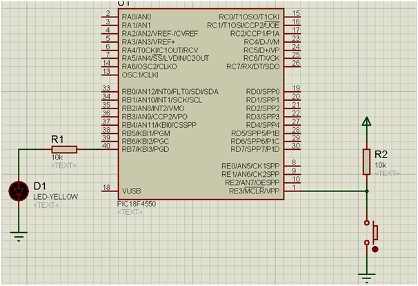
Figure 5: Full circuit for simulation
- Double click on PIC18F4550 will bring up Edit Component GUI. Here, you can set additional settings for your PIC. Then, load the hex code generated by the MPLAB in Program File column and click OK.
The sample source code using C18 is provided below.

Figure 6: Configuration in PIC18F4550
- At the far left, where the simulation panel is located, click on run to begin the simulation. Alternatively, you can pause, halt as well as simulation by frame.

Figure 7: Simulation panel
Source Code


Conclusion
This simulation will provide another platform to test and debug your PIC program in virtual environment. In addition, the developer can focus in troubleshooting their codes without having to worry about their hardware failure.
No comments:
Post a Comment