
Setting up and verified the oscillator's settings are essentially important in order to determine the timing. Some functions such as ADC, timer, interrupt, I2C, SPI, USB, CAN and Serial require the oscillator to be set first as the settings of these functions depends the frequency of the oscillator. There are two modes of oscillator's settings: Primary Oscillator and Secondary oscillator. The frequency that the PIC is oscillating is usually mistaken by taking the crystal oscillator directly. Instead, the frequency should be the frequency measured at CPU or peripherals after the multiplexer.
Steps in setting up oscillator
- Choose the frequency that you want your PIC to run. Lower frequency will gives more power saving while higher frequency will give better performance.
- If Serial communication is used, survey on the best frequency for you to choose to minimize the baud rate error. This will lower the ranges of frequencies you can choose .
- For higher accuracy, external crystal oscillator should be used.
- External crystal oscillator is chosen by selecting the best combination that can be found through the settings of PLLDIV and CPUDIV.
- USB usually requires 48MHz. Thus, this is provided by dividing the 96MHz frequency from the PLL by 2 or 48MHz can be supplied directly through the crystal oscillator. It can also be provided by dividing the primary clock by 4. Extra registers that has to be configured are USBDIV,FSEN, and FSOC3: FSOC0
- Use PLLDIV and CPUDIV with HSPLL, ECPLL, XTPLL, ECPIO or XT, HS EC and ECIO to get to the intended frequency as close as possible.
- A simple LED toggling code is used to verify the CPU frequency.
Examples using different compilers
MCC18
Information of definitions of the oscillator registers can be found in the PIC header files or directly in MPLAB.


This setting uses external crystal oscillator directly.
Sample LED toggling programme based on MCC18


HiTech C
Information of definitions of the oscillator registers can be found in the PIC header files.


The same configuration setting as shown using MCC18
Sample LED toggling program based on HiTech C
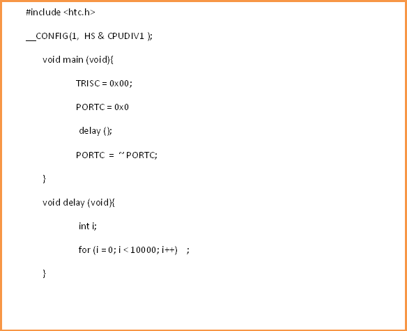

Figure 01: Sample programme based on HiTech C
Conclusion
Setting oscillator settings of any microcontroller is very important to ensure that our programs running correctly. Here, PIC18F4550 is chosen as an example but the settings of most microcontrollers are the same.
No comments:
Post a Comment